Gradys Simulations
Simulations from Project GrADyS on OMNET++ and INET framework
Introduction
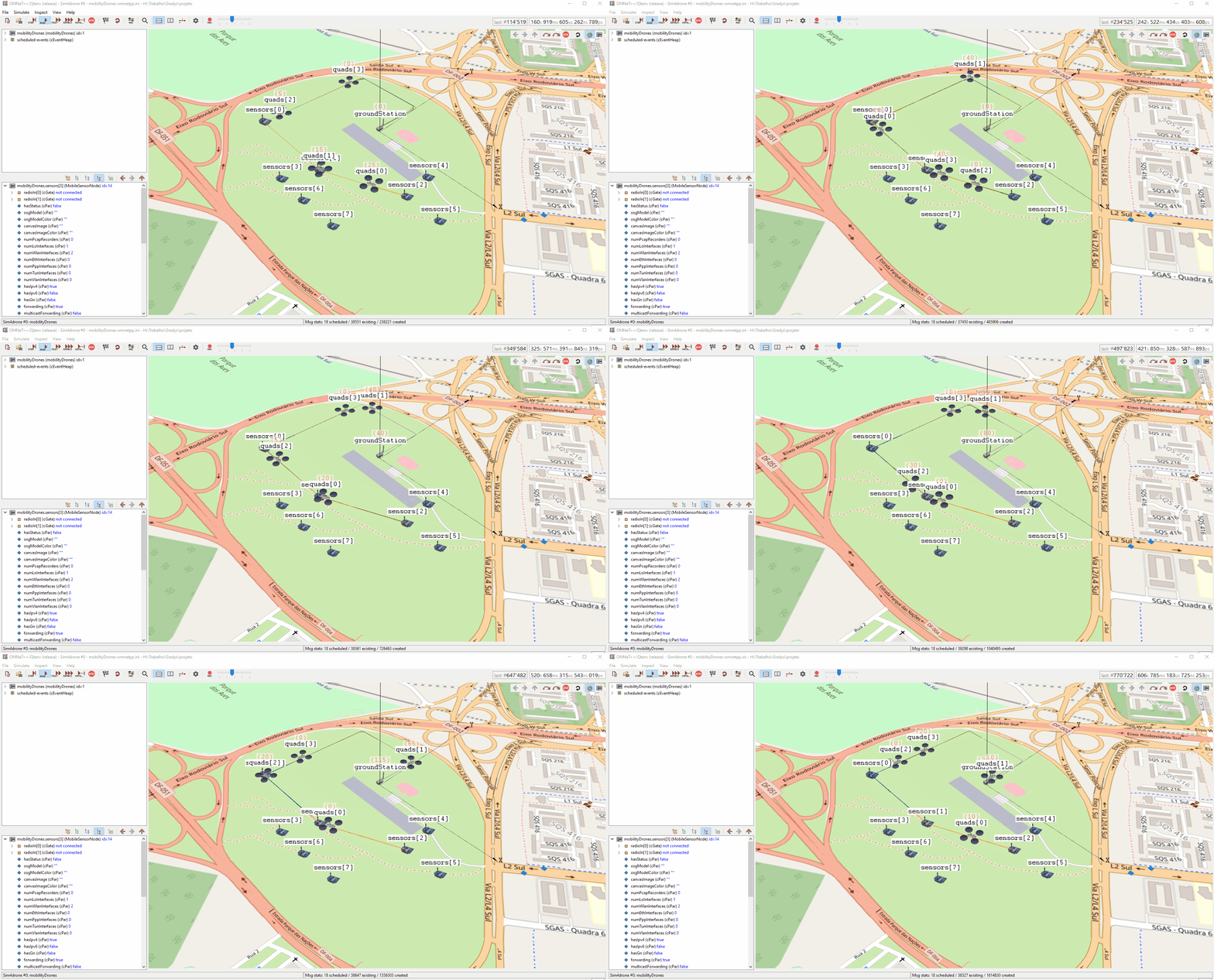
This is a repository for the simulation framework developed for the GrADyS project. This framework allows the simulation of interconnected network nodes and the implementation of UAV swarms and sensor coordination strategies with the objective of managing these autonomous UAV swarms to collect sensor data on the field autonomously and efficiently. Gradys Simulations MAVSIMNET a simulation framework for the OMNET++ discrete event simulator based on Ardupilot's Software In The Loop (SITL) simulator. It allows you to enrich OMNeT++ and INET's simulations with realistic mobility models for the mobile nodes in your network.
It works by spawning SITL instances that provide a physical simulation of the vehicle's behaviour and connecting them to the mobility classes in your simulation. A user can transparently use these mobility modules without worrying about the details of the communication and messages being exchanged between the network simulator and the SITL instances and a developer can use the strong interface provided in the project's base mobility class to implement his own mobility modules.
Installation
There are two ways to install and use Gradys-Sim. The first one is to download the provided virtual applience which you can import into any virtual machine software that supports the .ova file format. The second one it to install direcly into your machine
1. Virtualization
Just download the virtual applience file (.ova) from this link and import it into any virtual machine software that supports the .ova file format. There should be a user called "gradys" with password "gradys" already created on imported virtual machine. Oracle's VirtualBox is recommended.
Previous versions of this image:
2. Local Installation
In order to run the simulations and use the components in this repository you need to have both OMNeT++ and the INET framework installed.
Version 6.0.1 of OMNeT++ is required, to install it just follow these instructions. INET version 4.5.0 is also required, when first opening the OMNeT++ IDE you should be prompted with the option to install INET and all you need to do is accept it but if you need help check out the installation instructions.
After installing both OMNeT++ and INET you should be able to clone the repository to your active OMNeT++ IDE workspace. To do this select File > Import... then open the "git" section and select "Projects from git" then "Clone Uri". After that just fill in the URL for this repository and finish the process following the displayed instructions.
Make sure you have INET installed in your workspace and that it is selected as project reference. If you see a directory named inet, inet4.5 in your workspace INET is installed and you only need to check if its also selected for the gradys-simulations project. This can be done the following way: Right Click on gradys-simulations project -> Properties -> Project References. Make sure INET is selected here.
The sitl file for advanced mobility simulations are already included in the project. However if you would like to use newer versions, download the compiled SITL simulator for each vehicle type you want to use. Save the paths to these files as you will need them later. Binaries can be found on ardupilot's firmware website. These are the binaries for the most common platforms and supported vehicles:
| Vehicle | Windows | Linux |
|---|---|---|
| Copter | Link | Link |
| Plane | Link | Link |
| Rover | Link | Link |
The same applies to the parameter files for the vehilce types. There are already some defaults included in the project however if you would like to use different or check for the newest version do the following: Write or download parameter files for the vehicle types you want to use. Save the paths to these files as you will need them later. We recommend donwloading the default parameter files from here:
| Vehicle | Location |
|---|---|
| Copter | Link |
| Plane | Link |
| Rover | Link |
WARNING: You will need to modify the .ini file for the simulations and any other that you run to include your SITL installation paths and parameter file paths for each type of vehicle that you want to use.
Usage
OMNeT++ simulations are initialized by .ini files. The already provided omnetpp.ini files in the showcases contain some launch configurations for Wifi only communication and shared Wifi and MAM communication, each with configs for one to four UAVs. Launch configurations are defined in the same .ini file denoted by the [Config SOME_NAME]. The [Config Wifi] and [Config MAM] configs are base configs for the other ones and should not be ran.
All confiruation files are set to load the simulations on our field test location in Brasilia. If you want to change this you will have to chage these parameters:
# Scene's coordinates
*.coordinateSystem.sceneLongitude = -47.926634deg
*.coordinateSystem.sceneLatitude = -15.840075deg
*.coordinateSystem.sceneHeading = 90deg

# Vehicle's home coordinates
*.quads[*].mobility.homeLatitude = -15.840068deg
*.quads[*].mobility.homeLongitude = -47.926633deg

# Ground Station's coordinates
*.groundStation.mobility.initialLatitude = -15.840068deg
*.groundStation.mobility.initialLongitude = -47.926633deg

# Sensor's coordinates
*.sensors[0].mobility.initialLatitude = -15.84245230deg
*.sensors[0].mobility.initialLongitude = -47.92948720deg
Aditionally, the quads follow a series of waypoints specified in a waypoint file. You will also need to change these to reasonable waypoints on your simulation's location.
Example of a waypoint file:
# Numers 9,10 and 11 specify latitude, logitude and altitude
QGC WPL 110
0   1   0   16  0   0   0   0   -15.840075  -47.926634  0   1
1   0   3   22  0.00000000  0.00000000  0.00000000  0.00000000  -15.84008500    -47.92663560    20.000000   1
2   0   3   16  0.00000000  0.00000000  0.00000000  0.00000000  -15.84011710    -47.92712550    20.000000   1
3   0   3   16  5.00000000  0.00000000  0.00000000  0.00000000  -15.84019450    -47.92777060    20.000000   1
4   0   3   16  0.00000000  0.00000000  0.00000000  0.00000000  -15.84029000    -47.92860750    20.000000   1
5   0   3   16  5.00000000  0.00000000  0.00000000  0.00000000  -15.84019500    -47.92777060    20.000000   1
6   0   0   177 2.00000000  4.00000000  0.00000000  0.00000000  0.00000000  0.00000000  0.000000    1
7   0   0   20  0.00000000  0.00000000  0.00000000  0.00000000  0.00000000  0.00000000  0.000000    1
Recently some more showcases were added. They were created to test and measure the results of a simple simulation with a single drone collecting data from a couple of sensors. The simplicity of these simulations is intentional as it allows us to measure the effect that different parameters have on the collection rate and range of the vehicle. The configs set up simulation campaigns that help us figure out the parameters we should use to better reflect the numbers we observe on real-life experiments.
To aid us in interpreting this data we implemented data reporting to the modules used in these configs. When the parameter campaigns run they generate several .vec and other OMNeT++ statistical files. By using OMNeT++'s built in data analysis tools we can extrant information from these runs. To learn more about how to use these files to generate visualizations using the OMNeT++ IDE, check it's User Guida. Here are some examples:

Launch configurations dictate the parameters of your simulation and you can change omnetpp.ini to suit your necessities. Here are some of the more important parameters that you can try switching yourself:
The number of UAVs and sensors in the simulation:
*.numUAVs = 2 // Initializes the *.quad[] array with 2 UAVs
*.numSensors = 8 // Initializes the *.sensors[] array with 8 sensors
Some UAV (called quads in this file) parameters:
// The protocol the UAV will follow (protocols explained further bellow)
// Change this to test other protocols like "ZigzagProtocol"
*.quads[*].protocol.typename = "DadcaProtocol"

// The UAV's destination addresses (nodes it talks to and recieves messages from)
*.quads[0].app[0].destAddresses = "quads[1] sensors[0] sensors[1] sensors[2] groundStation"

// Start time for the UAV's communication and mobility modules
// Change this to expertiment with different start timings
*.quads[1].app[*].startTime = normal(40s, 1s) // Here the normal function gives a value 1s within 40s
*.quads[1].mobility.startTime = 40s

// The waypoint file the UAV should follow
*.quads[*].mobility.waypointFile = "paths/voo_ar.waypoints"
Some sensor parameters:
// The sensor's destination addresses
*.sensors[*].app[0].destAddresses = "quads[0] quads[1]"

// The protocol the sensor should follow
*.sensors[0..2].protocol.typename = "DadcaProtocolSensor"

// The sensor's position coordinates
*.sensors[0].mobility.initialLatitude = -15.84245230deg
*.sensors[0].mobility.initialLongitude = -47.92948720deg
To run a simulation simply select one of the .ini files in the showcases and use the OMNeT++ IDE Run option. After the GUI opens select the desired launch configuration and press play on the simulation.
For more realistic simulations
The mobility modules available in this framework are instances of INET mobility modules. If you do not know what those are or how to use them you can check INET's documentation. There you will learn how to set up a simulation environment, populate it with nodes and set them up with mobility modules. After your simulation is set up there is only a couple things you need to worry about.
A very important thing to take note of is that your simulation has to use INET's Real Time Scheduler. This guarantees that the SITL instances and OMNET++ are syncronized. You can set this up in your .ini file with this line:
scheduler-class = "inet::RealTimeScheduler"
Using the available mobility modules is as simple as setting your node's mobility module. You can do this with the following command, using the RandomWaypointMobility module as an example:
*.client[*].mobility.typename = "MAVLinkRandomWaypointMobility"
After placing this module in your simulation you need to set up the paths to the SITL simulators for each vehicle type supported. Currently you have to set up the copterSimulatorPath, planeSimulatorPath and roverSimulatorPath parameters. These are the paths to the files you have downloaded through out the installation, more specifically the path to the simulator binaries (.elf file on windows and extensionless file on linux). For example, if you ara on windows and have placed the copter simulator in the CopterSimulator file of the root directory of your C: drive, the parameter should be set to:
*.client.copterSimulatorPath = "PATH_TO_FILE/ArduCopter.elf"
Notice the escapes characters as windows uses back-slashes in paths.
INFO: If you are not using a vehicle type you can leave the path for that vehicle's simulator as an empty string.
After setting this up you need to pay attention to the module's required parameters. Those can be found in the module's documentation page. Remember to pay attention if the module extends another one, as the required fields for the latter will also need to be filled.
In general the parameters you need to fill when using any of the MAVSIMNET mobility models are:
| Parameter | Type | Description |
|---|---|---|
| vehicleType | int | MAVLink type of vehicle that this class represents (COPTER=1, PLANE=2, ROVER=4) |
| paramPath | string | Path for the parameters for this vehicle. These are the parameters you downloaded throughout the installation. Do not use parameters for a different vehicle type |
That is all you need to know if you plan to use this framework's existing modules with no modifications. If you plan on expanding upon it of modifying the modules there are a few more things you should be aware of.
Project Structure
Diagrams
Project Structure Diagram
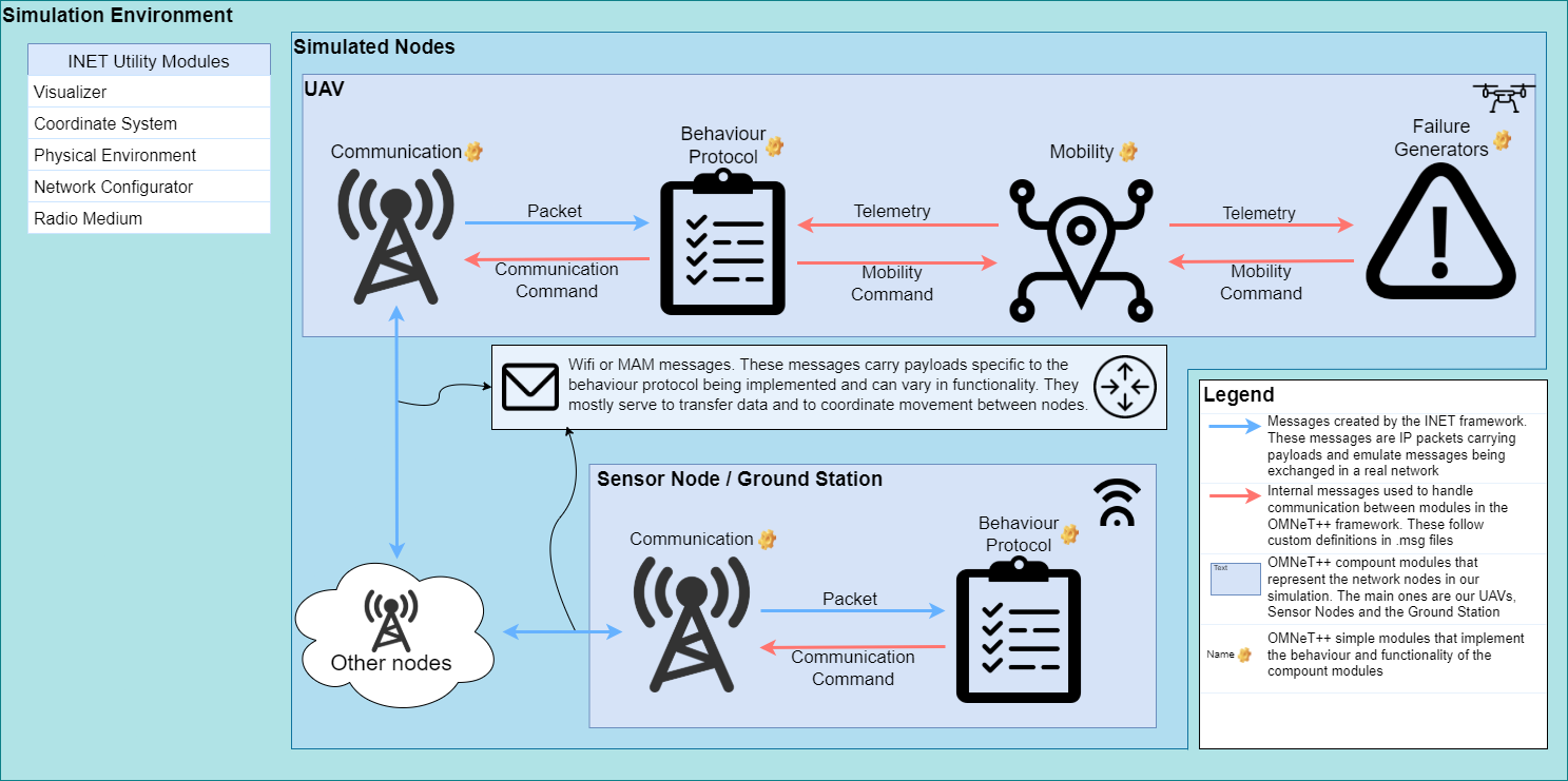
MAVSIMNET architecture diagram

Project Message Diagram
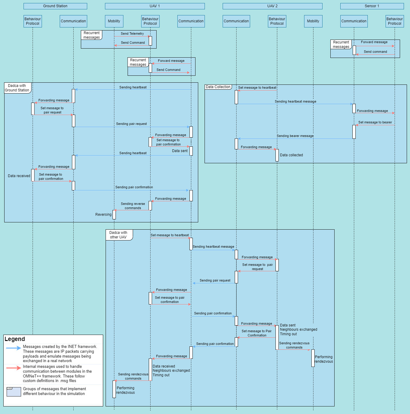
INET offers a series of modules that control node mobility. Our objective was to create a module that was capable of simulating a very simple UAV mobility model and could react to network events. This setup allows support for a wide array of possible UAV coordination protocols.
The described requirement was achieved with three modules, one resposible for communication between UAVs (communication), one for controlling the node's movement (mobility) and the last to manage the interaction between the last two (protocol). The behaviour and implementation of these modules is detailed further below. They were made in such a way that the messages exchanged between them are sufficiently generic to allow the creation of a new protocol by creating a new protocol module, with no changes to the other ones by levaraging these generic messages to carry out different procedures. The messages exchanged between them are explained further bellow and are contained on .msg files like MobilityCommand.msg, Telemetry.msg and CommunicationCommand.msg.
These three modules are loaded in a .ned file. In OMNeT++ .ned files define modules that can use other modules forming a module tree. These modules can be simple (the leaves of the module tree) or a compound module that connects simple modules or other compound modules with gates. A network is a special kind of compound module that can be run as a simulation.
The compound module that represents our UAVs is MobileNode.ned and MobileSensorNode.ned represents our sensors. These modules contain Communication and Mobility modules (defined in the extended module AdhocHost) and the Protocol module (defined in the file). The mobilityDrones.ned file connects all the UAVs(called quads), sensors and some other modules necessary to the simulation.
## Mobility The mobility module is responsible for controlling UAV movement and responding to requests from the protocol module to change that movement through MobilityCommand messages. It also needs to inform the procol module about the current state of the UAV's movement through Telemetry messages.
As part of the module initialization the waypoint list is attached to a Telemetry message so the protocol module has access to the tour the mobile node is following.
These are the messages used:
- MobilityCommand.msg
// Commands that the mobility module should be capable of carrying out
enum MobilityCommandType {
    // Makes the UAV reverse on its course
    // No params
    REVERSE=0;

    // Makes the UAV travel to a specific waypoint, following the tour pack
    // Param 1: Waypoint index
    GOTO_WAYPOINT=1;

    // Makes the UAV go to a specific coordinate and orient itself so it can continue the tour afterwards
    // Param 1: x component of the coord
    // Param 2: y component of the coord
    // Param 3: z component of the coord
    // Param 4: Next waypoint (Waypoint the UAV should go to after reaching the target)
    // Param 5: Last waypoint (Waypoint the UAV used to reach the coords)
    GOTO_COORDS=2;
}

// Message declaration containing the command Id and its parameters
message MobilityCommand {
    MobilityCommandType commandType;
    double param1=-1;
    double param2=-1;
    double param3=-1;
    double param4=-1;
    double param5=-1;
}
- Telemetry.msg
// Activity that the UAV is currently carrying out
enum DroneActivity {
    IDLE=0;
    NAVIGATING=1;
    REACHED_EDGE=2;
    FOLLOWING_COMMAND=3;
}

// Message declaration designed to share necessary UAV information with the communication module
message Telemetry {
    int nextWaypointID=-1;
    int lastWaypointID=-1;
    int currentCommand=-1;
    bool isReversed=false;
    DroneActivity droneActivity;
}
The only mobility module currently implemented is DroneMobility.ned which simulates the movement of a UAV.
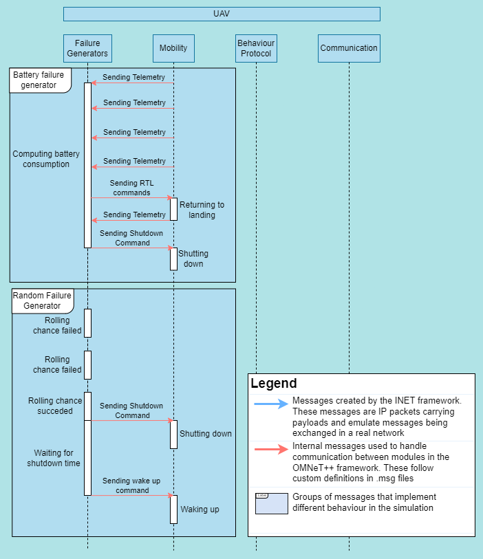
An optional feature of the mobility module is attaching a failure generator module. They connect to the mobility module using the same gates the protocol module does and use that to send commands in order to simulate failures. This can be used to trigger random shutdowns and even to simulate energy consumption. An example of a module that simulates energy consumption is the SimpleEnergyConsumption, a parametrized component to simulate consumption and battery capacity. It sends RETURN_TO_HOME messages to the vehicle when the UAV's battery reaches a certain threshold and shuts it down when the battery is depleted.
Configuring the use of failures for your mobile nodes is easy. The .failures[] array can be used to add as many failure generators as needed and the number of failures can be configured using the .numFailures option.
```python # Configuring two types of failures for quads[0]
.quads[0].numFailures = 2 # Two failures .quads[0].failures[0].typename="SimpleConsumptionEnergy" # The first one will use a simple energy consumption module .quads[0].failures[0].batteryCapacity = 5000mAh .quads[0].failures[0].batteryRTLThreshold = 4500mAh .quads[0].failures[0].batteryConsumption = 10A .quads[0].failures[0].rechargeDuration = 5s
.quads[1].failures[1].typename="RanfomFailureGenerator" # The second will use a random failure generator .quads[1].failures[1].failureStart = 10s .quads[1].failures[1].failureMininumInterval = 40s .quads[1].failures[1].failureChance = 0.001 ```
Heres a diagram illustrating the functionality of some of these models:
## Communication INET provides built in support for the simulation of real communications protocols and the communication module takes advantage of this to simulate communication between nodes. It also has to inform the protocol module of the messages being recieved by sharing the messages themselves and listen to orders from the protocol module through CommunicationCommands. Here are the messages used:
- CommunicationCommand.msg ```C++ enum CommunicationCommandType { // Sets the payload that the communication module sends SET_PAYLOAD=0; // Sets the target of the communication message (null means broadcast) SET_TARGET=1; }
// Message declaration for the communication command message CommunicationCommand { CommunicationCommandType commandType;
// Template for the SET_PAYLOAD message type (message that the communication module should send)
inet::FieldsChunk *payloadTemplate;

// Target for the set target command
string target;
} ```
The message module has several implementations. The base folder contains several base implementations for possible communication modules, these files contain functions that interface with INET's communication capabilities but don't implement interaction with any other module.
These files were used as base for the implementation of the communication modules. The following files are the implementations used in the simulations: * UdpMobileNodeCommunicationApp.ned
Manages the communication between mobile nodes and between mobile nodes and sensors.
-
UdpSensorCommunicationApp.ned
Manages communication between sensors and mobile nodes.
Protocol
The protocol module manages the interaction between the movement and communication of the mobile nodes. It makes use of the messages provided by it's two sibling modules to create node interaction strategies. It mostly reacts to messages it recieves from those modules and determines which orders to give them to achieve the desired result.
It gathers information about the current state of the simulation by analysing Telemetry messages recieved from the Mobility module and Packets forwarded to it by the Communication module. An important task it performs is the definition of the message sent by the Communication module. These messages will be sent to other nodes that will themselves handle them. The messages are inserted into IP Packages as payload. They can have different formats depending on the protocol being implemented. Here is the DadcaMessage.msg used by the Dadca protocol, for example.
- DadcaMessage.msg
enum DadcaMessageType
{
  HEARTBEAT = 0;
  PAIR_REQUEST = 1;
  PAIR_CONFIRM = 2;
  BEARER = 3;
}

class DadcaMessage extends FieldsChunk
{
  chunkLength = B(34); // Fixed chunk length
  int sourceID = -1;  // ID of the message's source
  int destinationID = -1; // ID of the message's destination
  int nextWaypointID = -1; // ID of the next waypoint
  int lastWaypointID = -1; // ID of the last waypoint
  int dataLength = 5; // Length of the imaginary data being carried in the message
  int leftNeighbours = 0; // Neighbours to the left of the UAV
  int rightNeighbours = 0; // Neighbours to the right of the UAV
  bool reversed = false; // Reverse flag which indicates the current direction the UAV is travelling in
  DadcaMessageType messageType = HEARTBEAT; // Type of message
}
Protocols implement an IProtocol interface and extend CommunicationProtocolBase.ned which provides useful stub functions to use when implementing protocols. These functions are as follows:
// Redirects message to the proper function
virtual void handleMessage(cMessage *msg);

// Handles package received from communication
// This packet is a message that was sent to the UAV
virtual void handlePacket(Packet *pk) {};

// Handles telemetry received from mobility
// The mobility module exchanges mobility information in the form of telemetry
virtual void handleTelemetry(Telemetry *telemetry) {};

// Sends command to mobility
virtual void sendCommand(MobilityCommand *order);
// Sends command to communication
virtual void sendCommand(CommunicationCommand *order);

// Sets a timeout
virtual void initiateTimeout(simtime_t duration);
// Checks if the module is timed out
virtual bool isTimedout();
These are the currently implemented protocols:
-
ZigZagProtocol.ned and ZigZagProtocolSensor.ned
These files implement the mobile node and the sensor side of the ZigZag protocol. This prococol manages a group of UAVs folowwing a set path passing above several sensors from where they pick up imaginary data from those sensors. The UAVs also interact with each other sending several messages to coordinate their movement.
Heartbeat messages are sent on a multicast address, if these are picked up by sensors they respond with data. If they are picked up by other UAVs they initiate a communication pair by sending a Pair Request message which is them confirmed by the other UAV with a Pair Confirmation message. The UAV furthest away from the starting point of the path sends its data to the other UAV in the pair and they both reverse their movement. The objective is that over time the UAVs will each occupy an equally sized section of the course, picking up data on the way and sharing it at their section's extremities.
-
DadcaProtocol.ned and DadcaProtocolSensor.ned
This protocol is similar to the ZigZagProtocol. It also manages data collection by mobile nodes in a set path. The difference is that this method aims to speed up the process of equally spacing the UAVs in the course by implementing a more advanced movement protocol.
When the Pair Confirmation message is recieved by both UAVs, confirming the pair, both UAVs take note of the number of neighours on their left (closer to the start) and their right (further from the start) and share this information with their pair. Both update their neighbour count and use it to calculate a point in the course that would represent the extremity of both their sections if their current count of neighbours is accurate. Them they both travel together to this point and revert. This behaviour is implemented with a sequence of commands that get queued on the mobility module.
Development
To develop new protocols, you will probably be creating new protocol modules that use the current message definitions and commands to implement new behaviour and management and data collection strategies. If the current set of commands and messages is not enough you are free to add more by modifying the message definitions and the modules so that they can properly react to these new messages.
After creating a new module all you need to do to test it is modifying the desired .ini configuration to load your protocol. The protocol module is flexible and can be loaded with any implemented protocol by changing it's typename, for example:
*.quads[*].protocol.typename = "DadcaProtocol"
Developing your own communication protocol
In this example we will develop a very simple protocol for our UAVs and sensors. Our UAVs will follow their waypoint paths without communication with each other, collecting data from sensors and depositing it at a central ground station. We will create sets of files (.ned, .h and .cc), SimpleDroneProtocol, SimpleSensorProtocol and SimpleGroundProtocol and a message declaration SimpleMessage.msg. For your convenience these files have already been created and placed in their respective folders, and the configuration file includes a launch config for this scenario.
Let's start with the message. Since this protocol is very simple we will implement a message with two fields, senderType and content.
SimpleMessage.msg
// communication/messages/network/SimpleMessage.msg

// Network messages need to extend from the FieldsChunk class or other chunk classes
import inet.common.packet.chunk.Chunk;

namespace inet;

enum SenderType
{
  DRONE = 0;
  SENSOR = 1;
  GROUND_STATION = 2;
}

class SimpleMessage extends FieldsChunk
{
    chunkLength = B(7); // Fixed chunk length
    SenderType senderType;
    int content;
}
Our protocols will use this message definition to communicate with eachother. Next let's define our UAV's protocol. All it needs to do is contantly emit messages with it's current data load, listen to messages from sensors to load more data and listen to messages from the groundStation to unload. The only parameter we are defining is the timeoutDuration, we will not override the default value but it is good to have the option to increase or decrease the UAV's timeout. This timeout will be activated to prevent over-communication with the sensors and ground station.
SimpleDroneProtocol.ned
// communication/protocols/mobile/SimpleDroneProtocol.ned

package gradys_simulations.communication.protocols.mobile;

import gradys_simulations.communication.protocols.base.CommunicationProtocolBase;

simple SimpleDroneProtocol extends CommunicationProtocolBase
{
    parameters:
        @class(SimpleDroneProtocol);
        @signal[dataLoad](type=long); // Declaration of dataLoad signal used to track current data load that the UAV is carrying
        double timeoutDuration @unit(s) = default(3s);
}
Note that we also included a signal declaration called dataLoad. Signals are messages that bubble up the module tree and can be used to track information from modules deeper in the tree. In this case whe have configured a statistic visualizer (provided by INET) to show this signal's state on the simulation screen.
omnetpp.ini
*.visualizer.*.statisticVisualizer.signalName = "dataLoad" # Signal name
*.visualizer.*.statisticVisualizer.format = "(%v)"
*.visualizer.*.statisticVisualizer.textColor = "red"
*.visualizer.*.statisticVisualizer.font = "Courier New, 12px, bold"
*.visualizer.*.statisticVisualizer.opacity = 1
*.visualizer.*.statisticVisualizer.sourceFilter = "*.quads[*].** *.groundStation.**"
Next we need to add code to our UAV module to simulate the required behaviours. Since our simple behavour only includes responding to messages from other nodes, we will only need to override the initialize and handlePacket functions. We will also create a updatePayload function that will update our message to include the current data content we collected.
SimpleDroneProcol.h
// communication/protocols/mobile/SimpleDroneProtocol.h

#include <omnetpp.h>
#include "../base/CommunicationProtocolBase.h"
#include "../../messages/network/SimpleMessage_m.h"

namespace gradys_simulations {

class SimpleDroneProtocol: public CommunicationProtocolBase {
    protected:
        simtime_t timeoutDuration;
        int content = 0;
    protected:
        // Performs the initialization of our module. This is a function that most OMNeT++ modules will override
        virtual void initialize(int stage) override;
        // Gets called when a packet is recieved from the communication module
        virtual void handlePacket(Packet *pk) override;
        // Helper function that updates packet content with the current collected data
        virtual void updatePayload();
};

} /* namespace gradys_simulations */
Our implementation of this header file is also very simple. Our initialization function will perform some startup tasks like setting our initial message and emitting a dataLoad signal so that the initial data load (0) will be displayed by the statistic visualizer described above. The UAV will increase it's content count every time it encounters another sensor message and transfer all it's data when it encounters a ground station message. Note: the par function loads the value specified in the .ned of ini files for that parameter.
SimpleDroneProtocol.cc
// communication/protocols/mobile/SimpleDroneProtocol.cc

#include "SimpleDroneProtocol.h"
#include "inet/common/ModuleAccess.h"
#include "inet/common/TagBase_m.h"
#include "inet/common/TimeTag_m.h"
#include "inet/common/packet/Packet.h"

namespace gradys_simulations {
Define_Module(SimpleDroneProtocol);

void SimpleDroneProtocol::initialize(int stage) {
    // Loading the parameter timeoutDuration
    timeoutDuration = par("timeoutDuration");

    // Emits the first dataLoad signal with value 0
    emit(registerSignal("dataLoad"), content);

    // Updates the payload so the UAV can start sending messages
    updatePayload();
}

void SimpleDroneProtocol::handlePacket(Packet *pk) {
    // Loads the SimpleMessage from the recieved packet
    auto message = pk->peekAtBack<SimpleMessage>(B(7), 1);

    if(message != nullptr) {
        switch(message->getSenderType()) {
            case DRONE:
            {
                std::cout << "Message recieved from drone, ignoring." << endl;
                break;
            }
            case SENSOR:
            {
                if(!isTimedout()) {
                    content += message->getContent();
                    // Emits signal and updates payload on data content change
                    emit(registerSignal("dataLoad"), content);
                    updatePayload();

                    initiateTimeout(timeoutDuration);
                }
                break;
            }
            case GROUND_STATION:
            {
                if(content != 0 && !isTimedout()) {
                    content = 0;
                    // Emits signal and updates payload on data content change
                    emit(registerSignal("dataLoad"), content);
                    updatePayload();

                    initiateTimeout(timeoutDuration);
                }
                break;
            }
        }
    }
}

void SimpleDroneProtocol::updatePayload() {
    // Creates message template with current content and correct type
    SimpleMessage *payload = new SimpleMessage();
    payload->addTag<CreationTimeTag>()->setCreationTime(simTime());
    payload->setSenderType(DRONE);
    payload->setContent(content);

    // Sends command to the communication module to start using this message
    CommunicationCommand *command = new CommunicationCommand();
    command->setCommandType(CommunicationCommandType::SET_PAYLOAD);
    command->setPayloadTemplate(payload);
    sendCommand(command);
}

} /* namespace gradys_simulations */
Next comes our sensor implementation. Here is the .ned file for our sensors:
SimpleSensorProtocol.ned
// communication/protocols/sensor/SimpleSensorProtocol.ned

package gradys_simulations.communication.protocols.sensor;

import gradys_simulations.communication.protocols.base.CommunicationProtocolBase;

simple SimpleSensorProtocol extends CommunicationProtocolBase
{
    parameters:
        @class(SimpleSensorProtocol);
        int payloadSize = default(5);
}
As you can see the file is very similar to the UAV's .ned file. The only big change is that our timeoutDuration parameter has been switched out for a payloadSize one. Our sensor is a passive listener so it doens't need a timeout. The payloadSize parameter defines the amound of data the sensor sends to the UAV during each communication. We will keep this at the default value 5 but you are free to change it.
SimpleSensorProcol.h
// communication/protocols/sensor/SimpleSensorProcol.h

#include <omnetpp.h>
#include "../base/CommunicationProtocolBase.h"
#include "../../messages/network/SimpleMessage_m.h"

namespace gradys_simulations {

class SimpleSensorProtocol: public CommunicationProtocolBase {
    protected:
        int payloadSize;
    protected:
        // Initialization function
        virtual void initialize(int stage) override;

        // Handles packet recieved from the UAV
        virtual void handlePacket(Packet *pk) override;
};

} /* namespace gradys_simulations */
SimpleSensorProcotol.cc
// communication/protocols/sensor/SimpleSensorProtocol.cc

namespace gradys_simulations {
Define_Module(SimpleSensorProtocol);

void SimpleSensorProtocol::initialize(int stage) {
    // Loading payload size parameter
    payloadSize = par("payloadSize");

    // Sets the correct payload
    SimpleMessage *payload = new SimpleMessage();
    payload->addTag<CreationTimeTag>()->setCreationTime(simTime());
    payload->setSenderType(SENSOR);
    payload->setContent(payloadSize);

    CommunicationCommand *command = new CommunicationCommand();
    command->setCommandType(CommunicationCommandType::SET_PAYLOAD);
    command->setPayloadTemplate(payload);
    sendCommand(command);
}

void SimpleSensorProtocol::handlePacket(Packet *pk) {
    // Loading message from packet
    auto message = pk->peekAtBack<SimpleMessage>(B(7), 1);

    if(message != nullptr) {
        switch(message->getSenderType()) {
            case DRONE:
            {
                // Sets the correct target
                CommunicationCommand *targetCommand = new CommunicationCommand();
                targetCommand->setCommandType(CommunicationCommandType::SET_TARGET);
                targetCommand->setTarget(pk->getName());
                sendCommand(targetCommand);
                break;
            }
            case SENSOR:
            {
                break;
            }
            case GROUND_STATION:
            {
                break;
            }
        }
    }
} /* namespace gradys_simulations */
When the sensor recieves messages from the UAVs they will set the UAV as a target (setting a target prevents the message from being broadcasted). The sensor's message is always the same, the only thing that changes is the target. The UdpSensorCommunicationApp communication module is programmed to be a passive communication module, that means that it doesn't send constant messages like the UdpMobileNodeCommunicationApp, it only sends messages when a new target or payload is set.
Last is the ground station. The ground station needs to listen to messages from UAVs and collect the data they are carrying and send a confirmation message back to the so they can empty their data load.
SimpleGroundProtocol.ned
// communication/protocols/ground/SimpleGroundProtocol.ned

package gradys_simulations.communication.protocols.ground;

import gradys_simulations.communication.protocols.base.CommunicationProtocolBase;

simple SimpleGroundProtocol extends CommunicationProtocolBase
{
    parameters:
        @class(SimpleGroundProtocol);
        @signal[dataLoad](type=long); // Declaration of dataLoad signal used to track current data load that the UAV is carrying
}
The ground station itself needs no parameters but it does need the dataLoad signal declaration so that it can properly display it's collected data. The implementation bellow is very similar to the sensor's code, the only thing changing is the message sender type.
SimpleGroundProtocol.h
// communication/protocols/ground/SimpleGroundProtocol.h

#include <omnetpp.h>
#include "../base/CommunicationProtocolBase.h"
#include "../../messages/network/SimpleMessage_m.h"

namespace gradys_simulations {

class SimpleGroundProtocol: public CommunicationProtocolBase {
    protected:
        int content = 0;
    protected:
        virtual void initialize(int stage) override;
        virtual void handlePacket(Packet *pk) override;
};

} /* namespace gradys_simulations */
SimpleGroundProtocol.cc
// communication/protocols/ground/SimpleGroundProtocol.cc

namespace gradys_simulations {
Define_Module(SimpleGroundProtocol);

void SimpleGroundProtocol::initialize(int stage) {
    emit(registerSignal("dataLoad"), content);

    // Sets the correct payload
    SimpleMessage *payload = new SimpleMessage();
    payload->addTag<CreationTimeTag>()->setCreationTime(simTime());
    payload->setSenderType(GROUND_STATION);
    payload->setContent(0);

    CommunicationCommand *command = new CommunicationCommand();
    command->setCommandType(CommunicationCommandType::SET_PAYLOAD);
    command->setPayloadTemplate(payload);
    sendCommand(command);
}

void SimpleGroundProtocol::handlePacket(Packet *pk) {
    auto message = pk->peekAtBack<SimpleMessage>(B(7), 1);

    if(message != nullptr) {
        switch(message->getSenderType()) {
            case DRONE:
            {
                content += message->getContent();
                // Emits signal on data content change
                emit(registerSignal("dataLoad"), content);

                // Sets the correct target
                CommunicationCommand *targetCommand = new CommunicationCommand();
                targetCommand->setCommandType(CommunicationCommandType::SET_TARGET);
                targetCommand->setTarget(pk->getName());
                sendCommand(targetCommand);
                break;
            }
            case SENSOR:
            {
                break;
            }
            case GROUND_STATION:
            {
                break;
            }
        }
    }
} /* namespace gradys_simulations */
After developing all our protocols, including .ned declarations and .h and .cc implementations and creating (or using an existing) message type, all that is left is creating a launch configuration that uses our protocol. This launch configuration is already in the omnetpp.ini file as [Config Simple]
[Config Simple]
# Sets the description of the launch configuration.
# Shown when you launch a simulation and are prompted to select the correct launch configuration.
description = "simple protocol configuration"

# UAV Configurations
# This parameter is declared in the mobilityDrones.ned network and defines the number of UAVs
# in the simulation.
*.numUAVs = 2

# Apps are user implemented modules that extend the behaviour of INET communication modules.
# In this case our app will be the communication part of our three part solution.
*.quads[*].numApps = 1

# The communbication module automatically filters messages from nodes that are not included in the
# destAddresses parameter. Be careful not to set the node as a destination address to itself.
*.quads[0].app[0].destAddresses = "quads[1] sensors[0] sensors[1] sensors[2] groundStation"
*.quads[1].app[0].destAddresses = "quads[0] sensors[0] sensors[1] sensors[2] groundStation"

# The waypointFile parameter is declared in DroneMobility.ned and specifies the waypoint list
# the UAVs will follow.
*.quads[0].mobility.waypointFile = "paths/voo_sensor1.waypoints"
*.quads[1].mobility.waypointFile = "paths/voo_sensor2.waypoints"

# The typename parameter of the protocol specifies the filename of the protocol implementation
# the protocol module will use.
*.quads[*].protocol.typename = "SimpleDroneProtocol"

# The normal() function gives us a value within 1s of 1s. This is used instead of a fixed value
# because if both the quads communication apps started at 1s and had the same interval between
# messages (defined by the .sendInterval parameter) they would be forever syncronized and their
# messages would always interfere with each other in the medium.
*.quads[0].app[*].startTime = normal(1s, 1s)
*.quads[1].app[*].startTime = normal(1s, 1s)

# Sensor configurations
*.sensors[*].app[*].destAddresses = "quads[0] quads[1]"
*.sensors[0..2].protocol.typename = "SimpleSensorProtocol"

# Groundstation configurations
# Setting the ground station as a sensor because it is a passive listener in this config
*.groundStation.app[0].typename = "UdpSensorCommunicationApp"
*.groundStation.app[*].destAddresses = "quads[0] quads[1]"
*.groundStation.protocol.typename = "SimpleGroundProtocol"
*.groundStation.app[0].startTime = 0s
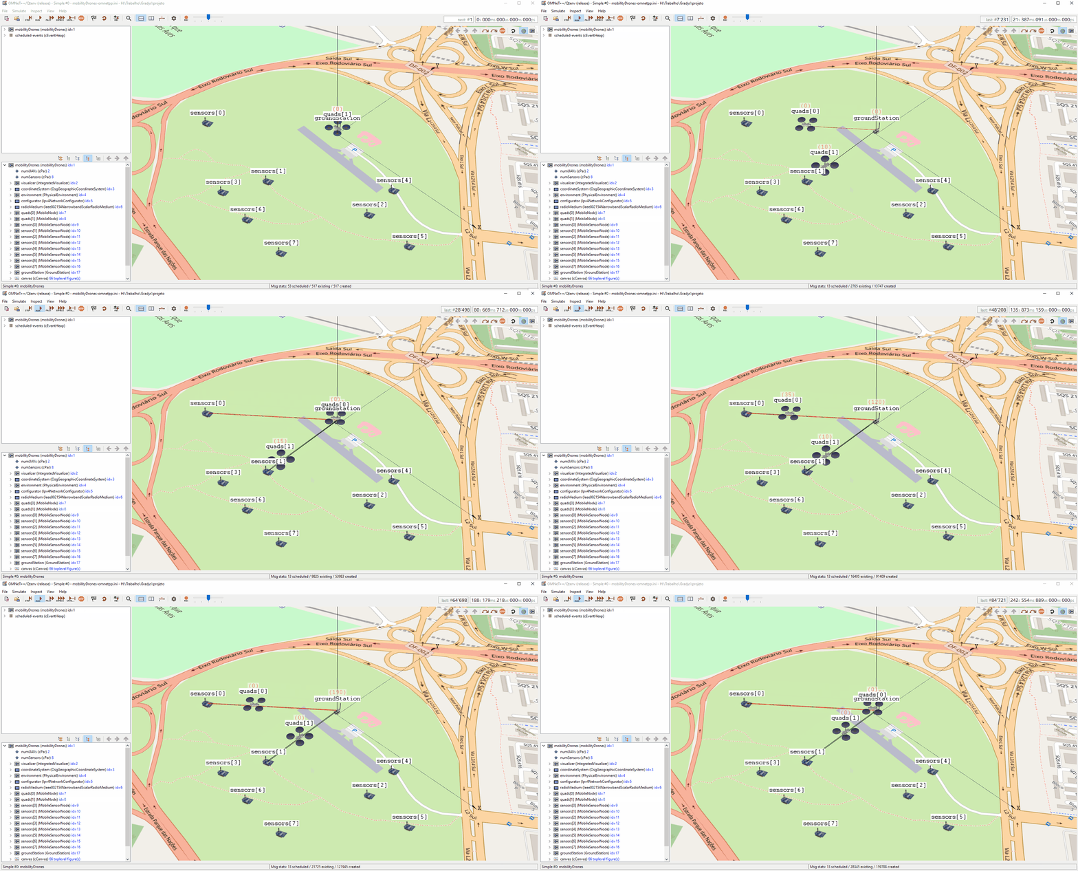
With all that you should be able to run the simulation and after selecting "Simple" as a launch configuration you will see the UAVs and sensors performing the described behaviour.
If you did everything right you should be seeing something like this:
You can find additinal information about this developing enviroment on the OMNeT++ and INET documentations. Sometimes some classes or functions are not that well documented, in that case looking at the samples and tutorials included with INET and OMNeT++ can be a useful resource and if even that doesn't help you can easily look at INET's source code as it should be included in your workspace if you installed it correctly.
MAVSIMNET Development
There are two important modules in the repository's utils folder that are useful for developers.
The VehicleRoutines module offers several utility functions that simplify common tasks using the MAVLink protocol. These functions generate a vector of instructions that should be queued using MAVLinkMobilityBase's queueInstructions function.
The other important module is the TelemetryConditions module. As explained in the MAVLinkMobilityBase documentation messages are dispatched to the SITL instance using a message queue. This message queue moves only when the front-most message is concluded. What defines a message as concluded is a function, called a Condition, that gets called on every telemetry received. This allows a developer to define the condition that needs to be fulfilled before the next message in the queue is sent. A takeoff message could wait for the vehicle to reach a certain altutde, for example. The TelemetryRoutines module has some ready-to-use conditions for these situations.
Project Configuration
Running Gradys Simulations Locally Without Docker
Setting Up Omnet++ and INet Locally for Running Gradys Simulations. This guide will walk you through the process of configuring Omnet++ on your local machine without the need for Docker. It covers both Linux and Windows systems and is divided into multiple sections for more clarity:
1) Installation of Omnet++ and INet
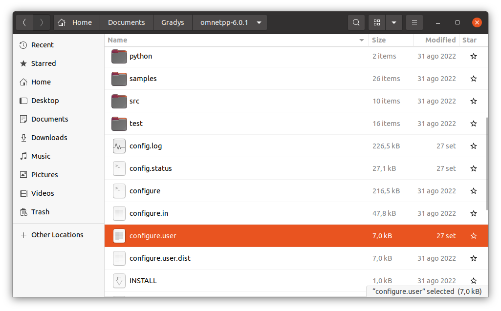
Before proceeding with the official installation instructions, it's essential to make adjustments to the configure.user file located in the Omnet folder where your project will be built. These adjustments are crucial for enabling the 3D visualization used in Gradys simulations. Ensure that both WITH_OSG and WITH_OSGEARTH are set to yes. You can find an exemplary version of the configure.user file in the docker_setup folder.
You can then follow the step-by-step installation procedures for Omnet++ and INet. Additionally, the simulation manual is also provided for reference:
- Omnet++ Installation Guide: https://doc.omnetpp.org/omnetpp/InstallGuide.pdf
- Omnet++ Simulation Manual: https://doc.omnetpp.org/omnetpp/manual/
2) Importing Projects
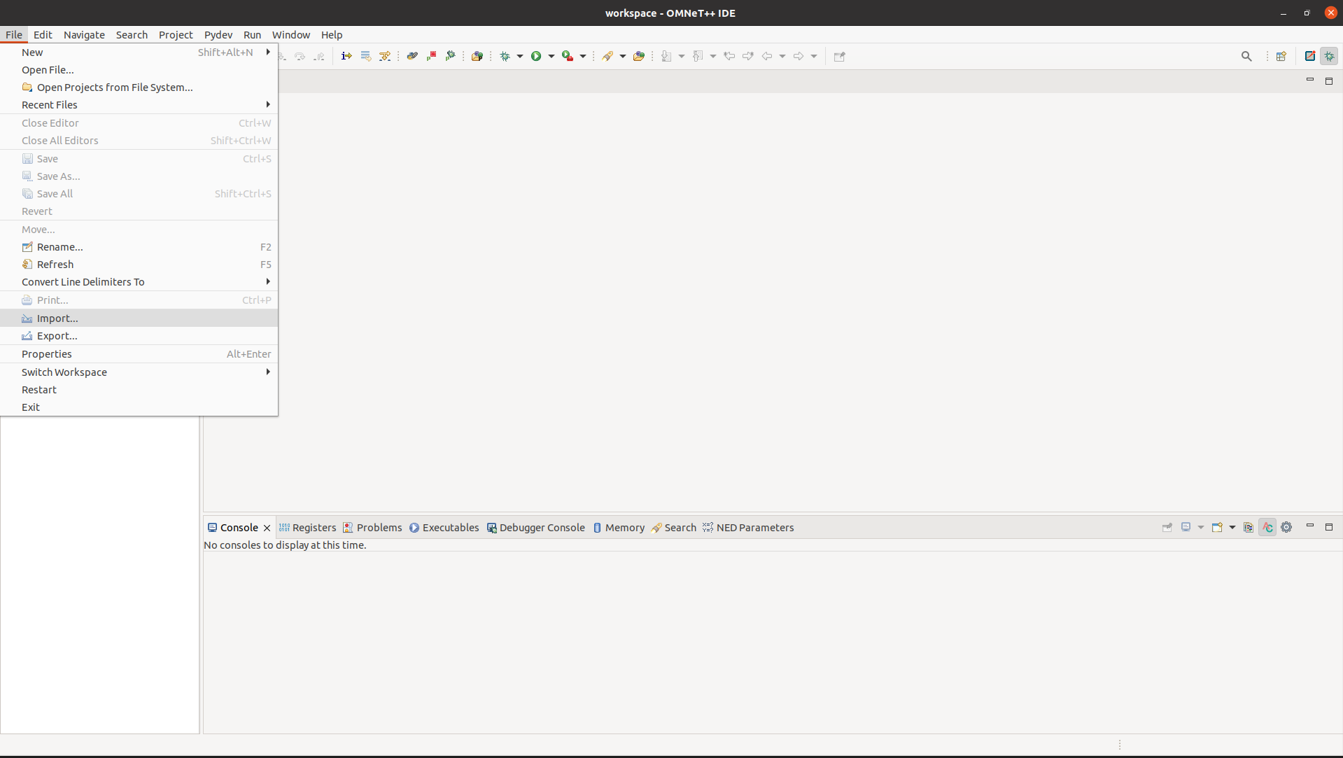
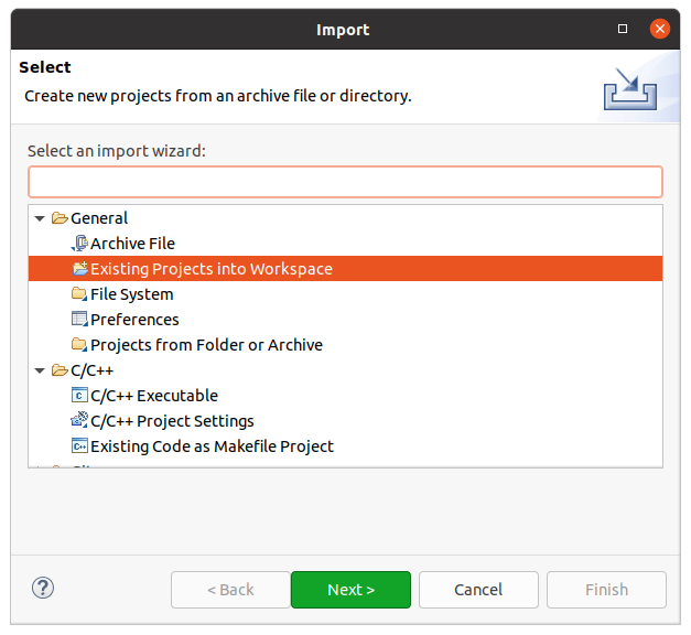
Once you have successfully installed Omnet++ and INet, you'll need to import the Gradys Simulations project and the INET project into your current workspace. You can do this as follows. Go to File -> Import -> Existing Projects into Workspace. Select the GradysSimulations Project and repeat the same for the INET Project. You can also refer to the provided screenshots for a visual guide on these steps.
3) Configuration of GradysSimulations and INet
After successfully installing Omnet++ and INet, the next step is to configure your integrated development environment (IDE) for GradysSimulations and INet to effectively run your project. This configuration process involves setting up various parameters and settings tailored to the specific requirements of Gradys Simulation.
- Configuration Gradys Simulation
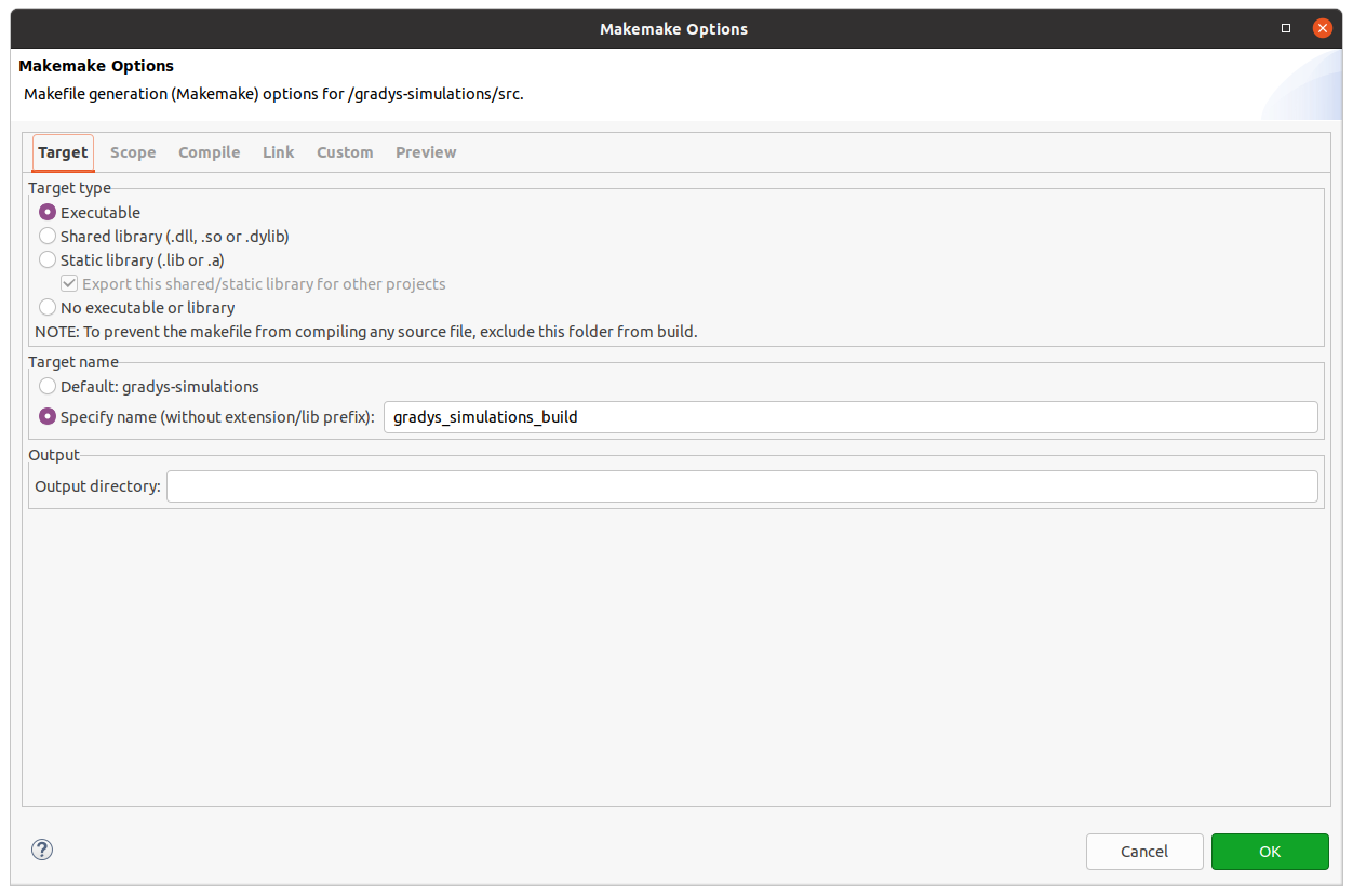
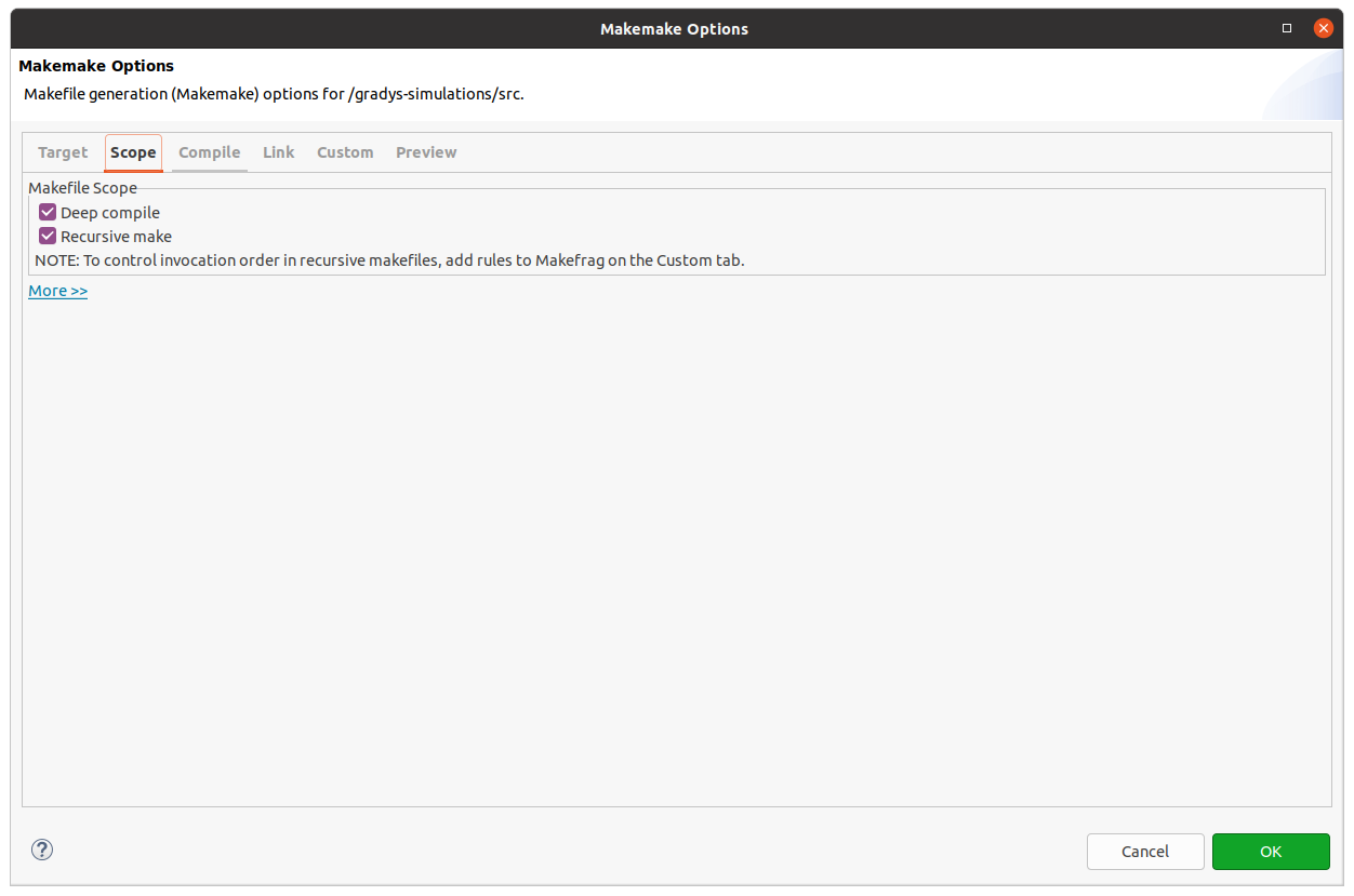
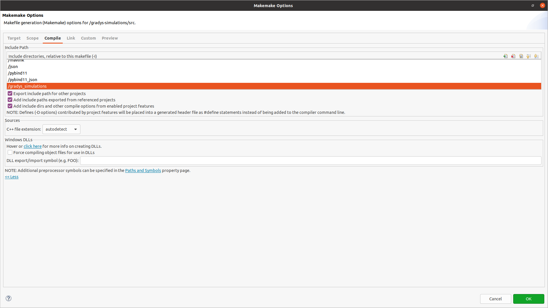
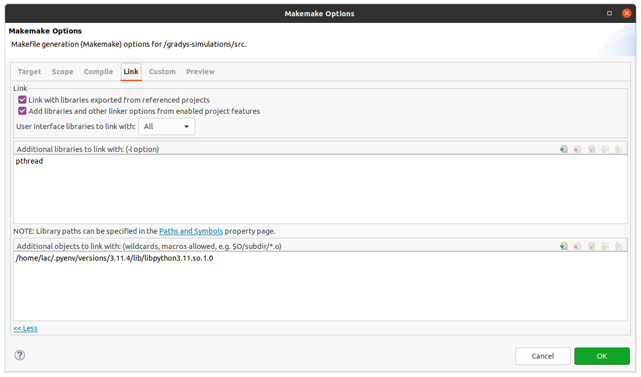
To run the Gradys Simulation project smoothly, several configurations must be in place, particularly regarding how the program locates includes for Python, JSON, Pybind, and Pybind JSON. These settings can be found within the "Paths and Symbols" configuration. You can access this configuration as follows: Right Click on your project -> Properties -> C/C++ General -> Paths and Symbols. Within the "Paths and Symbols" configuration, you will find three language tabs: Assembly, C, and C++. Since our imported projects only employ C++ for JSON, Pybind, and Pybind_JSON, you need to focus on the C++ tab. All other tabs should primarily include the project itself. For a visual guide on these steps follow step i, ii. In addition to that, the project's Makemake needs to be configured. In the Target tab it's important to specify a custom target name since the project otherwise has build problems. For the Compile it is important that all projects that are relative to the makefile and are used are imported. This means /mavlink, /json, /pybind11, /pybind11_json, /gradys_simulations, . . For the Linking tab it's important that additional libraries such as pthread and the path to the libpython are included. For a visual guide on these steps follow step iii. Last but not least we have to ensure that the python installation is correctly configured and we have our simulator package properly installed. For this we have to go into the PyDev - Interpreter / Grammar Settings and select our installed python environment in which we want to install the simulator package. In our case we have set up a new python installation with pyenv.One way of doing this is shown here: https://github.com/pyenv/pyenv. Afterwards we go into the python project and can run pip install . in the root of the project.
- Open Configuration Menu

- Configure Paths and Symbols
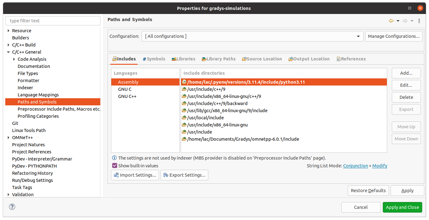
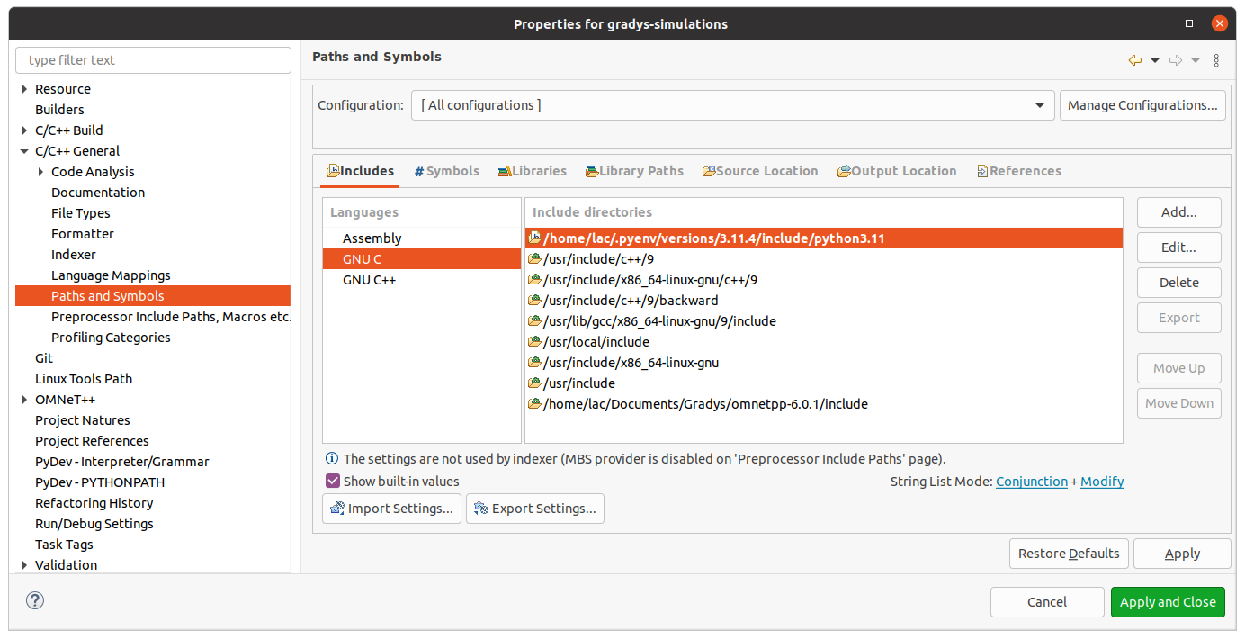
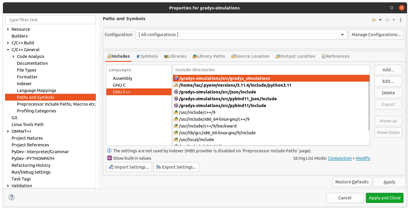
- Configure Project Makemake
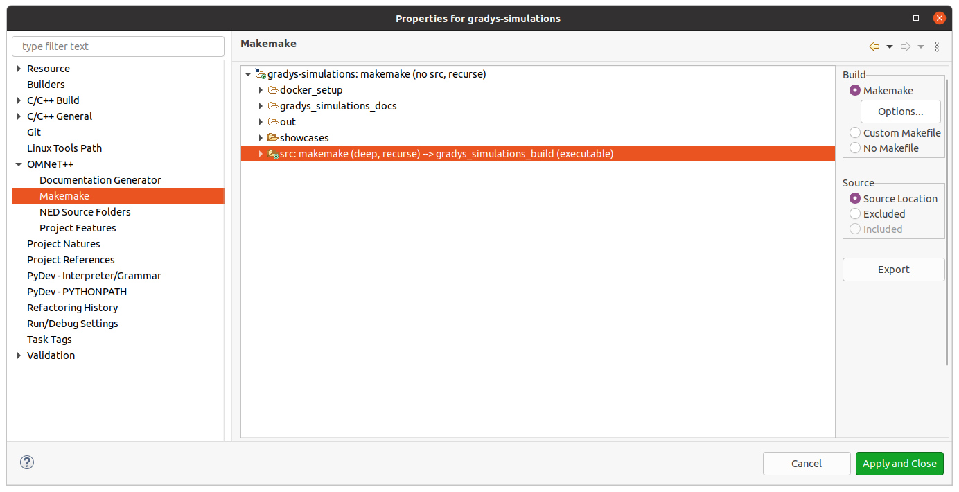
- Configure Python Environment

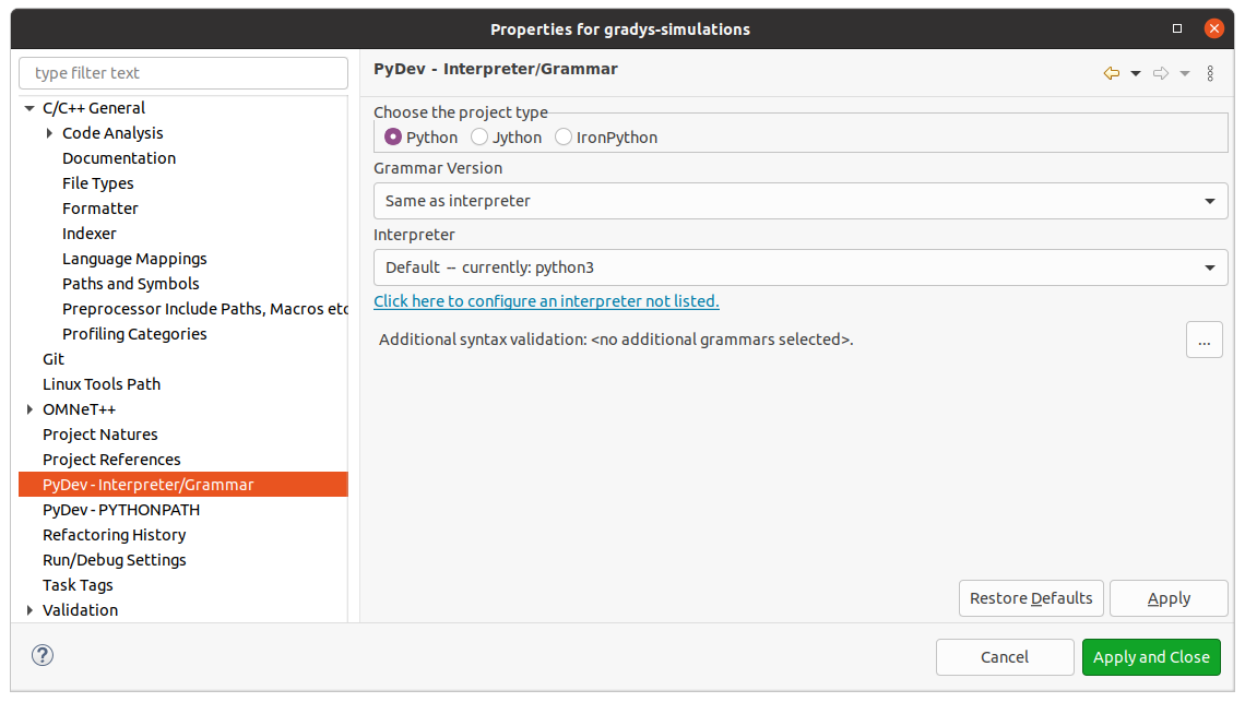
- Configuration INet
For the configuration of INet only the Project Features of the Omnet++ have to be adjusted. In particular we need to enable 3D Visualization. This is necessary so that we can have a nice visual presentation of our drones and sensors in Omnet++.


Running Gradys Simulations in Docker
This guide works under Linux and Windows (WSL2). In the following it is explained how to setup the Docker Container and open to Omnet++ IDE to run the GradysSimulations with Python and SITL extension. Additionally it will explain how to build the docker container on your own and how to configure it.
1) Running the docker container using the existing image: - Install Docker on your machine - Open a Terminal (on Windows use WSL2) - Run the following commands before pulling & running the docker image: > export DISPLAY=:0.0 > xhost +local:docker - Pull and run the docker image from docker hub > docker run -ti -e DISPLAY=$DISPLAY -v /tmp/.X11-unix:/tmp/.X11-unix kamysek/gradys-simulations bash - After the docker image is pulled and a bash opens, run the following command to start the preconfigured Omnet++ with Python extension > omnetpp
2) For building the docker image on your own machine use the following steps:
NOTE: In case changes to the code base were made and they required changes in the omnet setting e.g. updating paths / including imports. Make sure that those are also updated in the docker_setup folder. This folder contains basic ide settings as well as metadata information
- Install Docker on your machine
- Open a Terminal (on Windows use WSL2) in the directory of the Dockerfile
- Run the following command to build the image > docker build --build-arg OMNETPP_VERSION=6.0.1 --build-arg INET_VERSION=4.5 .
- After the image is successfully built check the image id and run the container > docker image ls > export DISPLAY=:0.0 > xhost +local:docker > docker run -ti -e DISPLAY=$DISPLAY -v /tmp/.X11-unix:/tmp/.X11-unix [IMAGE_ID] bash
- Now that the container is opened start omnetpp with the following command > omnetpp
- Afterwards select the workspace folder and make it your default. The folder is called
workspaceand is located in the home directory - Now that this is done make sure the correct INET project settings are enabled
- Afterwards you can run any showcase to experiment with omnetpp